
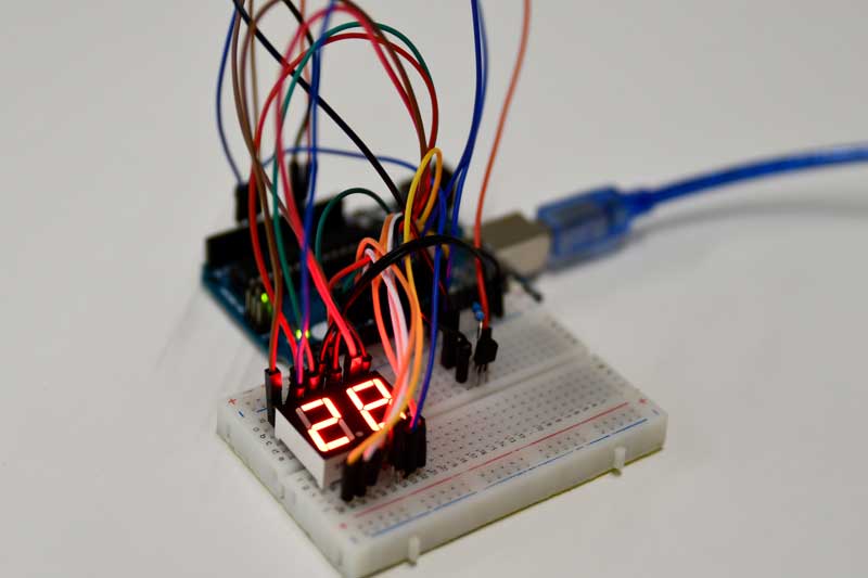
In this project you will learn how to make a thermometer with an Arduino. The temperatures that are measured will show you on a seven segment screen. As a sensor we use a DS18B20 temperature sensor. For the seven segment display we use a 2-digit 7-segment LED red.
- Level - Medium 45%
- Duration - 30/45 Min 45%
- Costs - € 41,84 euros complete 35%
Step 1: Requirements
- 1X Arduino UNO
- 1X Breadboard
- 19 times M/M jumper wires
- 1X 4,7K Ohm Resistor
- 1X DS18B20
- 1X 2-Digit 7-segment LED red
DS18B20 temperature sensor
The DS18B20 is a digital temperature sensor. That communicates easily with an Arduino through one data pin. The left pin of the sensor must be connected to the GND (-). The middle pin is connected to an analog data pin and the right one is connected to the VCC (5v). The DS18B20 is available in a waterproof and an unprotected version. The waterproof version is often used in liquids or damp areas. The “bare” sensor is often used to measure the outside temperature.
The DS18B20 can measure temperatures between -55 and 125 degrees Celsius. With an accuracy of 0,5 between -10 and 85. It is not recommended to expose the sensor to temperatures above 100 degrees Celsius. In principle, only the GND and the data pin are required to use this sensor. Only the values are so low that they cannot be read. To make the values higher, a “step-up” resistor must be used. In the case of this sensor, this is a 4,7K Ohm resistor that is placed between the VCC and the data connection.
2-digit 7-segment LED red
A 7-segment display comes in many different shapes and sizes. For this project we will use one with 2 numbers and 18 pins. The layout of the pins is shown in the image below. In this project we do not use the DP connections. As you can see in the image below, each “dash” has its own letter(s). In this project there is no room for personal input when connecting the display. If the order is not the same, the encoding will not work properly.
The display can get quite warm after long use. This can do no harm below 80 degrees Celsius.
Step 2: Building and Wiring
Now that you have all the parts you can start connecting the parts. Below you see a drawing how to connect the parts to the Breadboard and the Arduino. make sure that you connect the DS18B20 correctly, if you connect it the wrong way round, the sensor can be broken. The sensor has a flat and a convex side. The Flat side is the front. The ground pin is then on the left side.

Step 3: Programming
Most lines of coding are devoted to the 7-segment display. This requires a lot of coding because there is no simple library for it. In addition, the coding consists of some standard lines and the reading of the sensor.
In the beginning we make sure that everything is set up properly. You need to add the libraries for the sensor. Then indicate on which pin the data comes in. Then you enter that data into the libraries. Now we come to the part of the 7-segment display. We create an array. In this array we have to indicate how many digits we are going to add in this case 10 (0-90. We also have to indicate how many values there are per digit. Then you are going to indicate the data per digit. You do this by means of HIGH or LOW. 7 values you will give represents the 7 segments in the display (a, b, c, d, e, f, g) When a segment is set to HIGH, that segment will light up.
When you've done all this, we still need to make sure we can operate the numbers separately. We will do this by creating a 3rd and 4th void. We have to call these voids in the beginning. Now that all the preparation is done we go to the setup. Here we start the sensor and the serial communication. Then we indicate which pins are input and which are output, where pin 14 and 15 are analog pins A0 and A1.
Then we can start on the main coding. First we ask the sensor the values it measures. Then we add these values to a variable. This value is a number with two decimal places. This is a problem because we can only show 2 numbers. For the first digit (D1) we need to divide the value by 10 and then take the first digit before the decimal point. For the second digit (D2) we use the normal value and take the first digit before the decimal point. For example, with a value of 23,45 on D1 you would get 2 and on D2 you would get 3. We then need to translate these numbers so that the correct segments light up. We do this by referring to the 3rd and 4th void where we are going to do this translation. Finally, within the major coding, we write the temperature on the serial monitor.
The same coding is used for the 3rd and 4th void, just a different start pin. For this coding to work, it is important that the a/mg of a number is also connected consecutively. So from D1 a is on pin 2 and g is on pin 8. So to go to the next segment you can just add 1 to the variable for the pin.
Every we start the void by indicating where the a of that number is connected. Next, we create a for loop that plays itself a total of 7 times. This so that you go through all segments and all values that need to be entered. In this loop we start by telling him what to do with at the first pin. By referencing the array. Each time this void is repeated, 1 is added to the pin so it moves to the next segment.
This works the same for the 4th void. Only he has a different starting pin.
Hello:
Great post, personally I always used DS18B20 temperature sonsor in my project, because it s very easy to use, it only need 4.7K Resistor and example codefrom it library.