
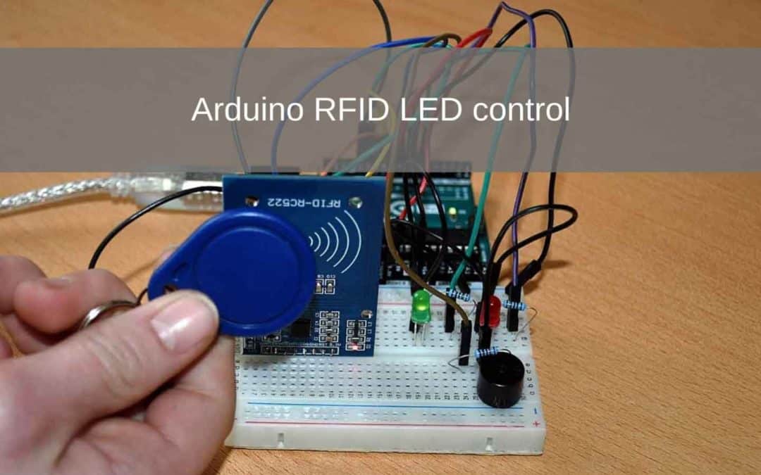
In this project I will show you how to connect an RFID reader to your Arduino yourself.
This project gives you a basic idea of how RFID works. We are going to let several LEDs light up with a Pass and a Keychain. When you are finished with this project you can, for example, control a servo to make an RFID Lock.
The codes required for this project can be tricky for beginners to understand.
Note: A soldering iron is required for this project.
- Level - Beginner / Advanced 50%
- Duration - 15 / 25Min 40%
- Costs - € 42,42 euros complete 35%
Step 1: Requirements
-
Sale!

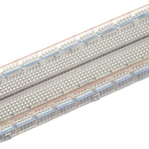
Breadboard 830 tie points
€6,95 /€5,74 excl. VAT -
Arduino Uno Rev3 – ATMEGA328
€23,95 /€19,79 excl. VAT -
Premium Jumper Wires 40pcs 20cm M / M
€3,45 /€2,85 excl. VAT -
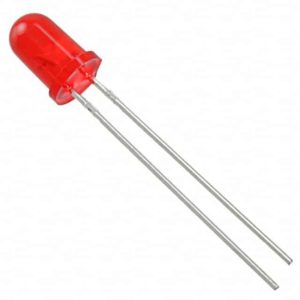
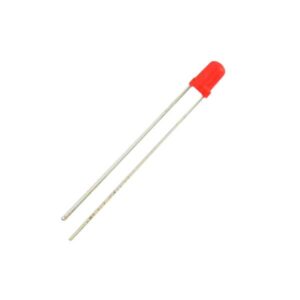
5mm LED Red
€0,29 /€0,24 excl. VAT -
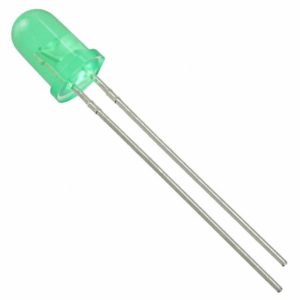
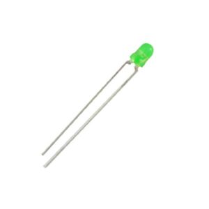
5mm LED Green
€0,29 /€0,24 excl. VAT -
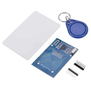
RFID Reader Kit
€5,95 /€4,92 excl. VAT -
Sale!
Breadboard 830 tie points – Transparent
€6,95 /€5,74 excl. VAT -
3mm LED Red
€0,24 /€0,20 excl. VAT -
3mm LED Green
€0,24 /€0,20 excl. VAT
Step 2: Building and Wiring
Now we are going to put the project together.
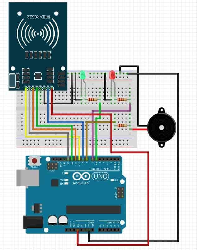
To start, we will solder the Pin header to the RFID Reader. We have chosen the curved headers because the reader then stands upright in the breadboard state.
Connect the components as indicated on the Fritzing below.
Step 3: Programming
Now that you're done wiring and building your Arduino RFID LED Controller, you can start programming the Arduino Uno.
We need to add a library for this code.
A Library or Include file often contains code that can often be reused in other Sketches. Often libraries (libraries) are a collection of related functions aimed at a particular application. For example to control a strip with LEDs, special mathematical functions or, for example, to control an LCD screen.
We use the library for the RFID Reader, otherwise the Arduino does not know what to do with the incoming data.
We do this by copying the folder MFRC522 or moving it to the folder libraries.
this folder is normally found in https://www.arduinolibraries.info/libraries/mfrc522 of https://github.com/ljos/MFRC522
We used version 1.4.5 for this library.
You can copy the code below to the Arduino IDE.
//electronicsvoorjou.nl
// Download the MFRC522 library here: https://github.com/ljos/MFRC522 or https://www.arduinolibraries.info/libraries/mfrc522
#include
#include
// Indicates the pins
#define SS_PIN 10
#define RST_PIN 9
// Indicates to which pin the LED is connected
const int ledpin1 = 7;
const int ledpin2 = 6;
const int buzzer = 8;
// Creates own veriable for card reader
MFRC522 myReader (SS_PIN, RST_PIN);
void setup ()
{
// set buzzer to pin 8 as output
pinMode (buzzer, OUTPUT);
// Start communication with the monitor
Serial.begin (9600);
// Library SPI
SPI.begin ();
// Up to version 1.4.5 this call
myReader.PCD_Init ();
// Print on monitor: “..”
Serial.println (“Present your key-tag”);
Serial.println ();
// initialize pin 7 and 6 as output
pinMode (ledpin1, OUTPUT);
pinMode (ledpin2, OUTPUT);
}
void loop ()
{
// see if no new maps are detected
digitalWrite (ledpin1, HIGH);
if (! myReader.PICC_IsNewCardPresent ())
{
// not found, stops searching
return;
}
// Checks whether the key tag can be read
if (! myReader.PICC_ReadCardSerial ())
{
// failed to read
return;
}
// Show UID on serial monitor
String key = "";
for (byte i = 0; i <myReader.uid.size; i ++)
{
key.concat (String (myReader.uid.uidByte [i] <0x10? ”0 ″:” “));
key.concat (String (myReader.uid.uidByte [i], HEX));
}
// Uppercase code of found key for better comparison
key.toUpperCase ();
// Print to monitor so you know which key is being read
Serial.println ();
Serial.print (“key tag is:“);
Serial.print (key);
// Grants access if key “..” is the same
// Each key tag has its own code, read your code via monitor
Serial.println ();
Serial.print ("Access:");
if (key == ”93 F9 BE A9 ″)
{
// Red LED off, green turns on
digitalWrite (ledpin1, LOW);
digitalWrite (ledpin2, HIGH);
// Determines the frequency of the buzzer
tone (buzzer, 1000);
// wait 1 second
delay (1000);
// stops sound
noTone(buzzer);
// Print on monitor
Serial.print (“Issued”);
delay (3000);
digitalWrite (ledpin1, HIGH);
digitalWrite (ledpin2, LOW);
}
else {
// Red LED on, green off
digitalWrite (ledpin1, HIGH);
digitalWrite (ledpin2, LOW);
// Determines the frequency of the buzzer
tone (buzzer, 500);
// wait 1 second
delay (1000);
// stops sound
noTone(buzzer);
// Print on monitor
Serial.print (“Not issued”);
delay (3000);
}
Serial.println ();
}
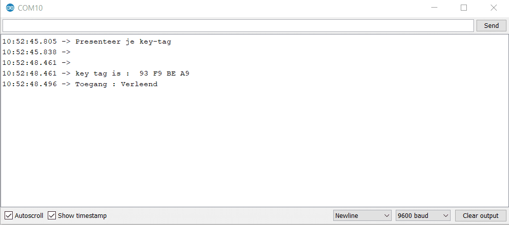
Since each RFID only has a different basic value, we must first read it out.
We do this by opening the serial monitor in the top right corner of the Arduino IDE. If you now hold a card for the RFID reader, a value will appear. See the picture below.
You have to paste this value into the code for (key == ”_____”) here comes the value of your pass.
The value associated with this corresponds in this case to the green LED.
The red LED lights up on all cards that are not recognized.
You are now done with this project. Add a relay and servo yourself to make your own RFID lock!
Too bad but doesn't work.
Serial.print (“Not Issued”);
stray '\ 342' in program
Hello Arie,
A stray 342 usually refers to a copy error.
Try typing the code. Will it work?