4.7 avg.
5183+ reviews5183+ reviews
Order by 16:00 for same day shipping
14 days return
EN
Individual
Business
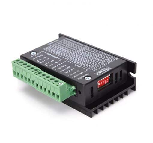
TB6600 Stepper Motor Driver
Description TB6600 Stepper Motor Driver
The TB6600 stepper driver is a professional and user-friendly module. The driver can control two-stage stepper motors. It works with a 5V digital pulse signal. So you can control it with an Arduino microcontroller, for example. It has a wide range of 9 to 42 VDC and is able to deliver a peak current of 4A. This is sufficient for most stepper motors.
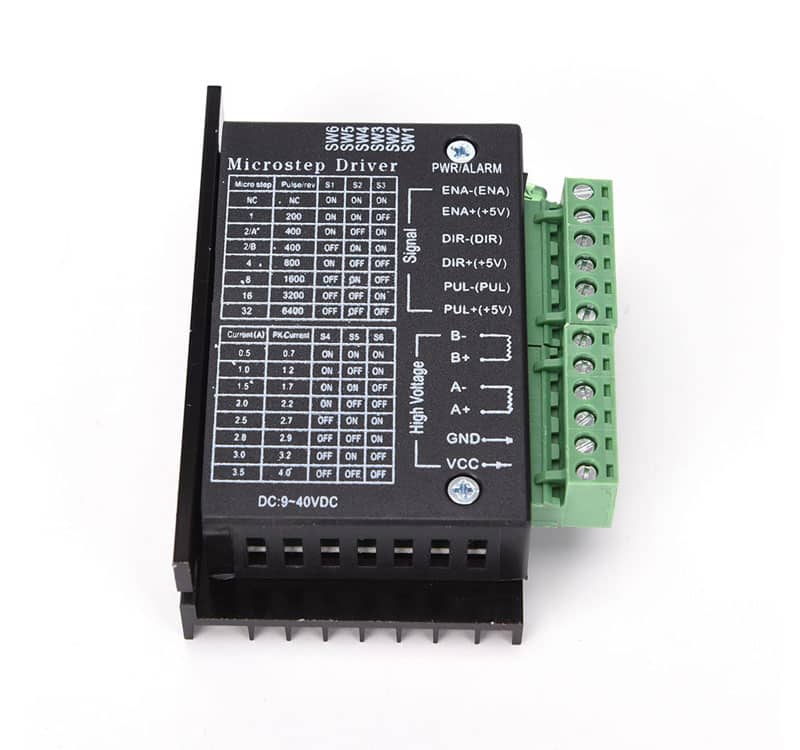
TB6600 supports speed and direction control. With 6 DIP switches on the side, you can set the microstep and output current. There are 7 kinds of microsteps in total: 1, 2/A, 2/B, 4, 8, 16, 32
There are 8 types of current regulators: 0.5A, 1A, 1.5A, 2A, 2.5A, 2.8A, 3.0 A, 3.5A
Specifier TB6600 Stepper Motor Driver
- 9V-42V DC power supply.
- Output current: 0.5A-4.0A.
- Driving mode: dual constant current PWM drive output.
- Strong anti-interference ability.
- Low vibration, low noise.
- Insulation resistance:>500MΩ at normal temperature and pressure.
- Insulation strength: 500V/min at normal temperature and pressure.
- With overheating, overcurrent, undervoltage lock, input voltage anti-reverse protection and other functions.
- Can drive 4-wire, 6-wire, 8-wire stepper motors.
- Cooling method: natural cooling or forced air cooling.
- Storage temperature: -20°C-65°C.
- Ambient humidity: <80% RH, no condensation, no frost.
- Vibrations: maximum not more than 5.7 m/S2.
- Use occasions: Avoid dust, oil and corrosive gases, and prohibit flammable gases and conductive dust.
- The pulse and directional signal lines and the motor and power supply lines must not be located next to each other, preferably at least 10 cm apart.
- If one power supply is used for multiple drives, parallel connections must be made on the power supply. It is not allowed to go to each other and then to another chain connection.
- Do not connect or disconnect the power connector of the drive when the power is on. When the driven motor stops, there is still a large current flowing through the coil. If you pull the power connector, the driver will be burned.
- It is strictly forbidden to access the terminal after wire head plus tin, otherwise the terminal may be overheated and damaged due to the increase in contact resistance.
- The wiring heads must not be exposed beyond the terminal blocks to prevent accidental short circuit and damage to the inverter.
TB6600 Stepper Motor Driver
In stock
€19.96
Order before 4:00 PM = shipped today
Free shipping from €99.95
14 days free returns
Same-day pickup at our office in Leusden
5183+ reviews
4.7 avg.
5183+ reviewsSKU: RDV3003 Categories: 3D Printer Parts , Servo's & Motors , Drivers
Description TB6600 Stepper Motor Driver
The TB6600 stepper driver is a professional and user-friendly module. The driver can control two-stage stepper motors. It works with a 5V digital pulse signal. So you can control it with an Arduino microcontroller, for example. It has a wide range of 9 to 42 VDC and is able to deliver a peak current of 4A. This is sufficient for most stepper motors.
TB6600 supports speed and direction control. With 6 DIP switches on the side, you can set the microstep and output current. There are 7 kinds of microsteps in total: 1, 2/A, 2/B, 4, 8, 16, 32
There are 8 types of current regulators: 0.5A, 1A, 1.5A, 2A, 2.5A, 2.8A, 3.0 A, 3.5A
Specifier TB6600 Stepper Motor Driver
- 9V-42V DC power supply.
- Output current: 0.5A-4.0A.
- Driving mode: dual constant current PWM drive output.
- Strong anti-interference ability.
- Low vibration, low noise.
- Insulation resistance:>500MΩ at normal temperature and pressure.
- Insulation strength: 500V/min at normal temperature and pressure.
- With overheating, overcurrent, undervoltage lock, input voltage anti-reverse protection and other functions.
- Can drive 4-wire, 6-wire, 8-wire stepper motors.
- Cooling method: natural cooling or forced air cooling.
- Storage temperature: -20°C-65°C.
- Ambient humidity: <80% RH, no condensation, no frost.
- Vibrations: maximum not more than 5.7 m/S2.
- Use occasions: Avoid dust, oil and corrosive gases, and prohibit flammable gases and conductive dust.
- The pulse and directional signal lines and the motor and power supply lines must not be located next to each other, preferably at least 10 cm apart.
- If one power supply is used for multiple drives, parallel connections must be made on the power supply. It is not allowed to go to each other and then to another chain connection.
- Do not connect or disconnect the power connector of the drive when the power is on. When the driven motor stops, there is still a large current flowing through the coil. If you pull the power connector, the driver will be burned.
- It is strictly forbidden to access the terminal after wire head plus tin, otherwise the terminal may be overheated and damaged due to the increase in contact resistance.
- The wiring heads must not be exposed beyond the terminal blocks to prevent accidental short circuit and damage to the inverter.