4.7 avg.
5183+ reviews5183+ reviews
Order by 16:00 for same day shipping
14 days return
EN
Individual
Business
GPIO Project 11 - Security System with Keypad
Beginner
30 Minuten
113,90
In this project you will learn how to build a simple security system using a 4x4 keypad, an RGB LED and the GPIO pins of the Raspberry Pi . This project uses Python and the Thonny IDE, available by default in Raspberry Pi OS.
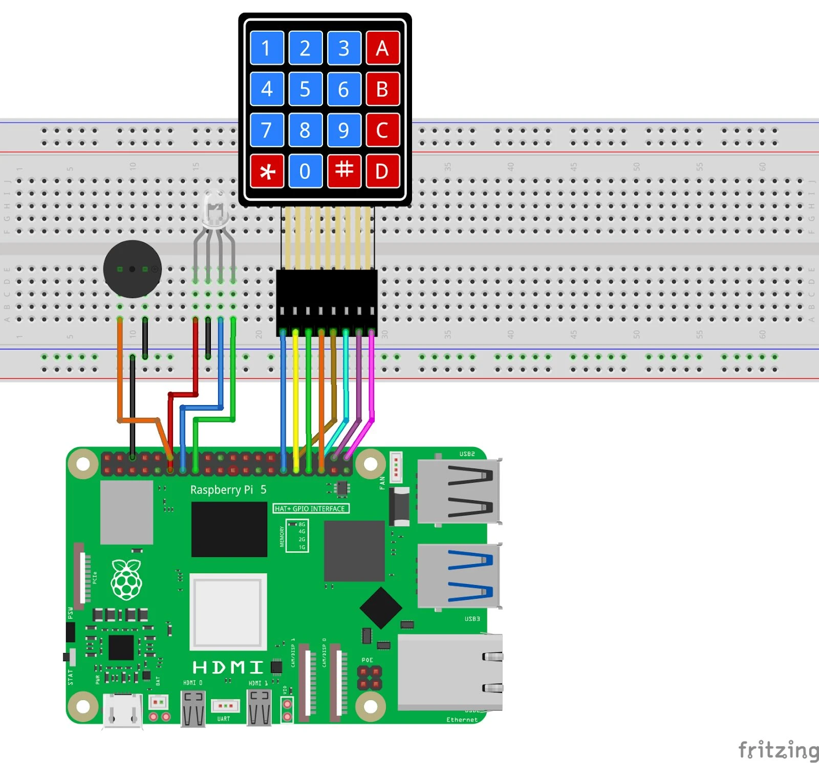
Connection diagram
- Connecting RGB LED:
- Place the RGB LED on the breadboard.
- Connect the RGB LED to GPIO 17 (red), GPIO 27 (green) and GPIO 22 (blue).
- Connect the common cathode (long pin) to GND (pin 6) of the Raspberry Pi .
- Connecting the keypad:
- Connect the 4 rows of the keypad to GPIO 5, 6, 13 and 19.
- Connect the 4 columns of the keypad to GPIO 12, 16, 20 and 21.
- Connecting the buzzer (optional):
- Connect the positive pin of the buzzer to GPIO 18.
- Connect the negative pin to GND.
Pinout Reference
Component | GPIO Pin | Physical Pin |
| RGB Red | GPIO 17 | Pin 11 |
| RGB Green | GPIO 27 | Pin 13 |
| RGB Blue | GPIO 22 | Pin 15 |
| Keypad Rows | GPIO 5, 6, 13, 19 | Pin 29, 31, 33, 35 |
| Keypad Columns | GPIO 12, 16, 20, 21 | Pin 32, 36, 38, 40 |
| Buzzer (optional) | GPIO 18 | Pin 12 |
Python code in Thonny
- Start Thonny: Click on the Raspberry Pi menu > Programming > Thonny Python IDE.
- Write your code: Create a new file in Thonny and enter the following code:
import RPi.GPIO as GPIO
from time import sleep

# Pin-definities
RED_PIN = 17
GREEN_PIN = 27
BLUE_PIN = 22
BUZZER_PIN = 18

ROWS = [5, 6, 13, 19]  # GPIO-pinnen voor rijen
COLS = [12, 16, 20, 21]  # GPIO-pinnen voor kolommen

# Keypad lay-out
KEYS = [
    ['1', '2', '3', 'A'],
    ['4', '5', '6', 'B'],
    ['7', '8', '9', 'C'],
    ['*', '0', '#', 'D']
]

PINCODE = "1234"  # Stel de gewenste pincode in

# GPIO setup
GPIO.setmode(GPIO.BCM)
GPIO.setup([RED_PIN, GREEN_PIN, BLUE_PIN, BUZZER_PIN], GPIO.OUT)

for row_pin in ROWS:
    GPIO.setup(row_pin, GPIO.OUT)
    GPIO.output(row_pin, GPIO.LOW)

for col_pin in COLS:
    GPIO.setup(col_pin, GPIO.IN, pull_up_down=GPIO.PUD_DOWN)

def set_color(r, g, b):
    """Stelt de kleur van de RGB LED in."""
    GPIO.output(RED_PIN, r)
    GPIO.output(GREEN_PIN, g)
    GPIO.output(BLUE_PIN, b)

def read_key():
    """Leest een toets van het 4x4 Keypad."""
    for row_num, row_pin in enumerate(ROWS):
        GPIO.output(row_pin, GPIO.HIGH)
        for col_num, col_pin in enumerate(COLS):
            if GPIO.input(col_pin) == GPIO.HIGH:
                GPIO.output(row_pin, GPIO.LOW)
                return KEYS[row_num][col_num]
        GPIO.output(row_pin, GPIO.LOW)
    return None

try:
    while True:
        print("Voer de pincode in:")
        input_code = ""  # Variabele wordt hier correct gedefinieerd als lege string

        # Lees de pincode van het keypad
        while len(input_code) < len(PINCODE):
            key = read_key()
            if key:
                print(f"Toets ingedrukt: {key}")
                if key in ['*', '#', 'A', 'B', 'C', 'D']:
                    print("Speciale toets genegeerd.")
                    continue
                input_code += key  # Voeg de toets toe aan de pincode
                sleep(0.3)  # Voor debounce

        # Controleer de ingevoerde code
        if input_code == PINCODE:
            print("Correcte pincode!")
            set_color(0, 1, 0)  # Groen
        else:
            print("Foute pincode!")
            set_color(1, 0, 0)  # Rood
            GPIO.output(BUZZER_PIN, GPIO.HIGH)
            sleep(0.5)
            GPIO.output(BUZZER_PIN, GPIO.LOW)

        sleep(2)
        set_color(0, 0, 0)  # LED uit
except KeyboardInterrupt:
    print("Programma gestopt.")
finally:
    GPIO.cleanup()
Save the file: Click File > Save As and name the file keypad_security.py .
Run the script: Click the green Run button (▶) at the top of the Thonny interface.
How does it work?
- Correct PIN code: The RGB LED lights up green.
- Incorrect PIN code: The RGB LED lights up red, and the buzzer (if present) beeps briefly.
Input: The system waits for an input from the keypad and compares it with the set PIN code.
Result
If everything is connected correctly and the code is running, the security system will work as follows:
- If input is correct, the RGB LED will light up green.
- If an incorrect input is entered, the RGB LED will light up red and the buzzer will warn.
Experimenting
- Other Colors: Use different combinations of the RGB LED to provide more feedback.
- More complex PIN: Add additional logic to support longer or complex PINs.
- Additional alarm: Connect a siren or other actuator for a more comprehensive system.