4.7 avg.
5150+ reviews5150+ reviews
Order by 16:00 for same day shipping
14 days return
EN
Individual
Business
GPIO Project 4 - Push button (digital/analog)
Beginner
30 Minuten
114,90
In this project you will learn two ways to use a push button:
- Digital use : The pushbutton is connected to a GPIO pin of the Raspberry Pi and controls an LED via a Python program.
- Analog use : The push button is connected directly into a simple circuit to control an LED, without GPIO or programming intervention.
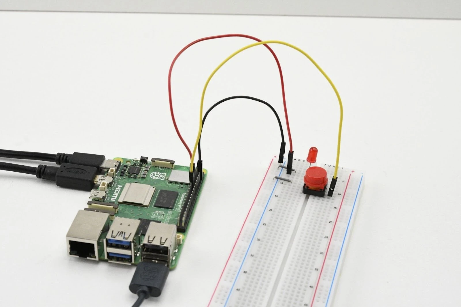
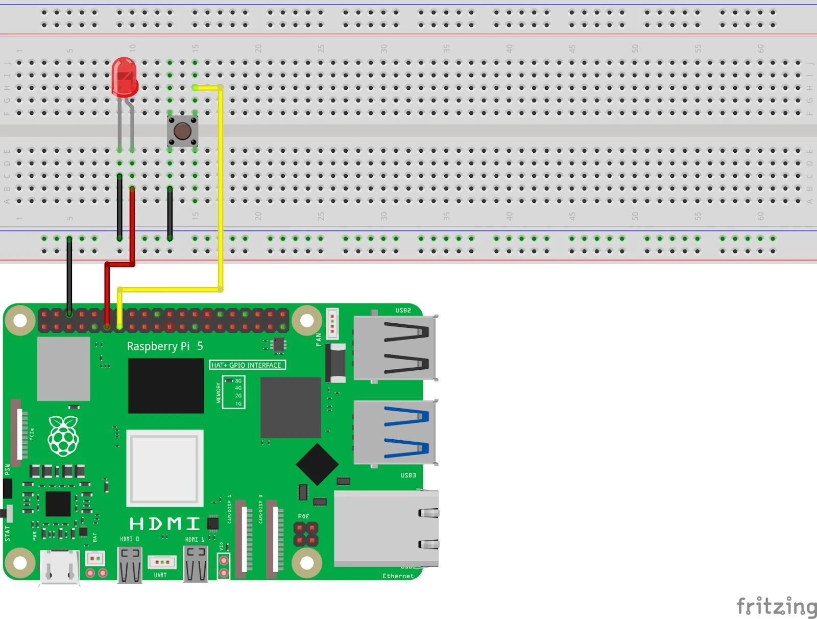
Digital Push Button
Connection diagram
- Connect the push button:
- One side of the push button:
- Connect to GPIO 17 (pin 11) .
- Connect to GND (pin 6) .
- The other side of the push button:
- Connect to 3.3V (pin 1) .
- One side of the push button:
- Connect the LED:
- Long leg (anode) :
- Connect this to GPIO 27 (pin 13) .
- Short leg (cathode) :
- Connect to GND (pin 6) .
- Long leg (anode) :
Pinout Reference
GPIO | Pin # | Function | Connection |
| GPIO 17 | Pin 11 | Digital input | Push button |
| GPIO 27 | Pin 13 | Digital output | LED |
| GND | Pin 6 | Earth (Ground) | Push button & LED |
Python code in Thonny
- Write your code: Open the Thonny Python IDE and enter the following code:
from gpiozero import LED, Button
from signal import pause

# LED en drukknop koppelen aan GPIO-pinnen
led = LED(27)       # LED op GPIO 27
button = Button(17) # Drukknop op GPIO 17

# Actie koppelen: LED aan bij knop indrukken
button.when_pressed = led.on
button.when_released = led.off

print("Druk op de knop om de LED te bedienen!")
pause()  # Houd het programma actief
2. Save the file : Click File > Save As and name the file button_led_digital.py .
3. Run the script : Click the green Run button (▶) at the top of the Thonny interface.
How does it work?
- Button(17) : Configures GPIO 17 as an input pin for the pushbutton.
- when_pressed and when_released : Determines what happens when the button is pressed or released.
- pause() : Keeps the script running until you manually stop it.
Result
- Press the button: The LED turns on.
- Release the button: The LED turns off.
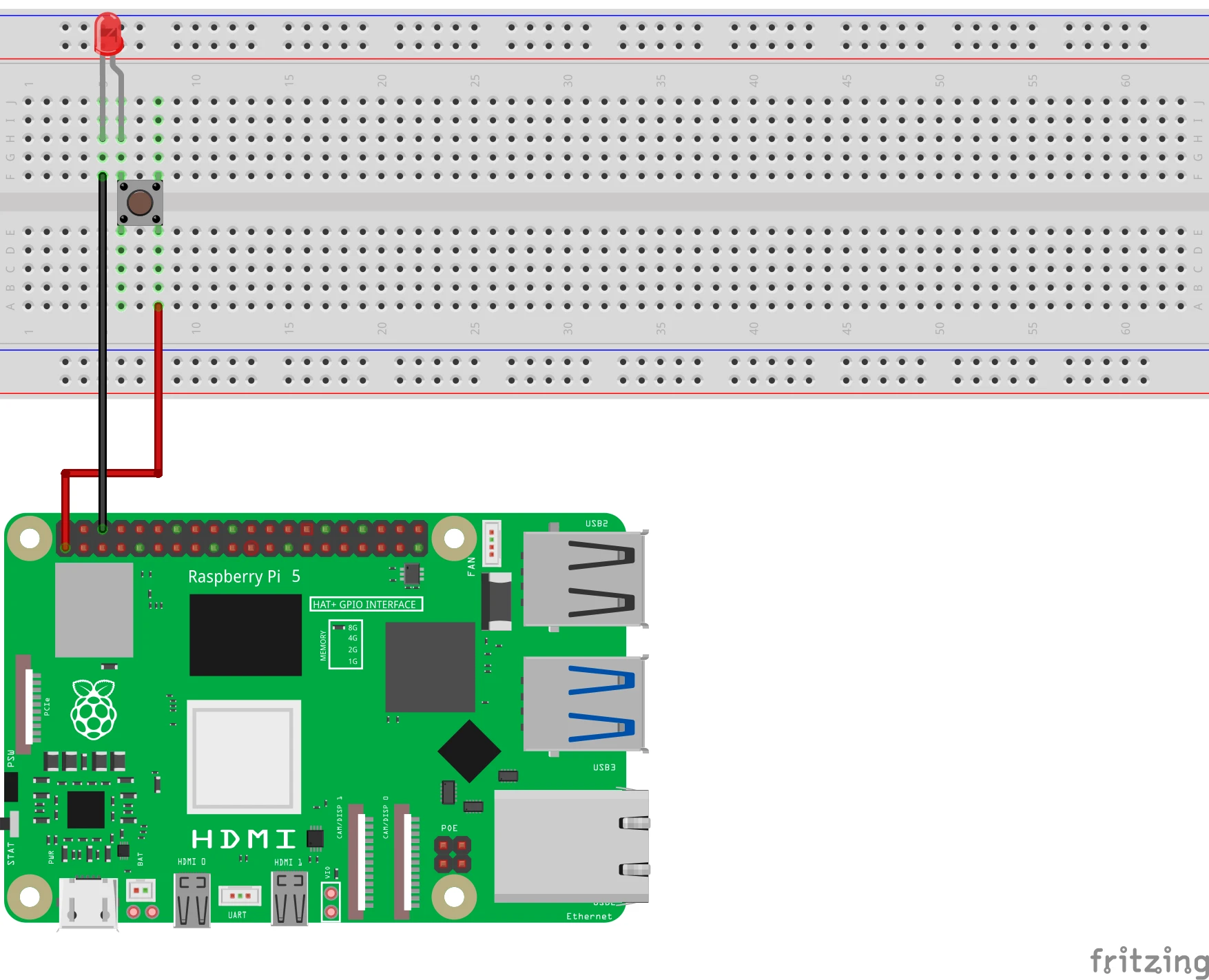
Analog Usage
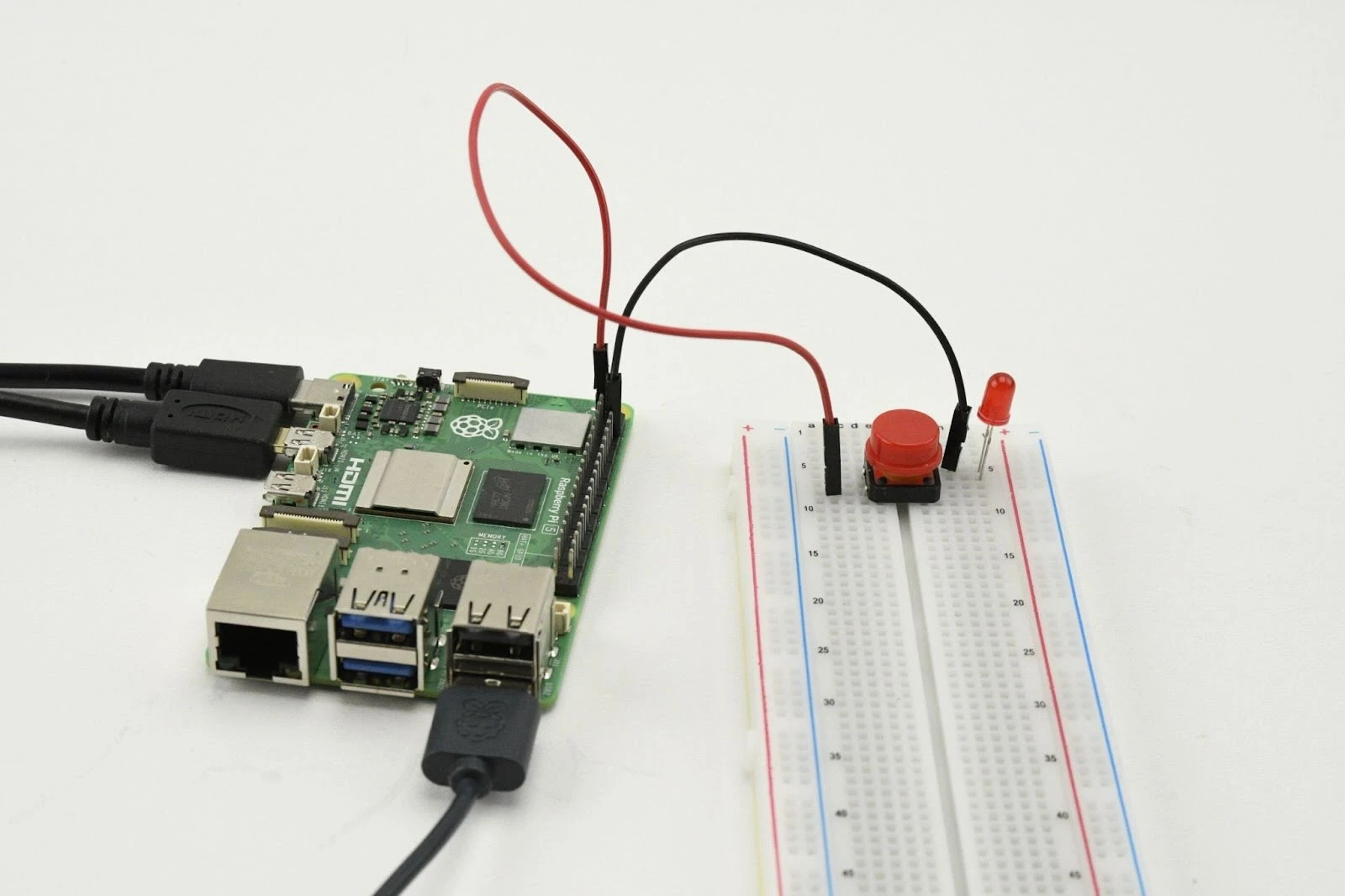
- Connect the push button:
- One side of the push button:
- Connect to the long leg (anode) of an LED.
- The other side of the push button:
- Connect to a 220Ω resistor , and connect the other side of the resistor to +3.3V (pin 1) .
- One side of the push button:
- Connect the LED:
- Short leg (cathode) of the LED is connected directly to GND (pin 6) .
Pinout Reference
Pin | Function | Connection |
| Pin 1 | 3.3V Power Supply | One side of the push button |
| Pin 6 | Earth (Ground) | LED cathode |
How does it work?
- When you press the push button, you immediately close the circuit between the 3.3V power supply and the LED.
- This turns on the LED without any GPIO or programming intervention.
Result
- Press the button: The LED turns on.
- Release the button: The LED turns off.
Experimenting
- Expanding digital use:
- Let the LED flash as long as the button is pressed:
from gpiozero import LED, Button
from time import sleep

led = LED(27)
button = Button(17)

while True:
    if button.is_pressed:
        led.on()
        sleep(0.5)
        led.off()
        sleep(0.5)
    else:
        led.off()
2. Combining analog and digital:
- Use one pushbutton for the analog circuit and a second pushbutton for digital control via GPIO.
After this project you can move on to the next project:
https:// electronicsforyou.com/project/gpio-project-5-ldr-introduction